Phase Error
The phase error is defined as the difference between the ideal insertion phase and the actual insertion phase referenced to the reference phase state. The reference phase state usually refers to the “all zero” state.
When calculating RMS phase error in a n-bit phase shifter it is important to use the correct calculation. Datasheets typically show phase delta compared to a reference state (usually the “all zero” state). If these phase deltas are used to calculate the RMS phase error then the result will in general be pessimistic. This is because the average of phase delta errors over all states is unlikely to be mean-zero. A consequence of this is that the RMS phase error calculated this way depends on which state is chosen as the reference state.
The correct way to calculate RMS phase error is to subtract the mean error in delta phase. This is the squared sum of errors term in parentheses:

The table below illustrates the effect of not subtracting the average phase error with different reference states (Error 1 and Error 2) and the correct calculation using the same reference states (Error 3 and Error 4):
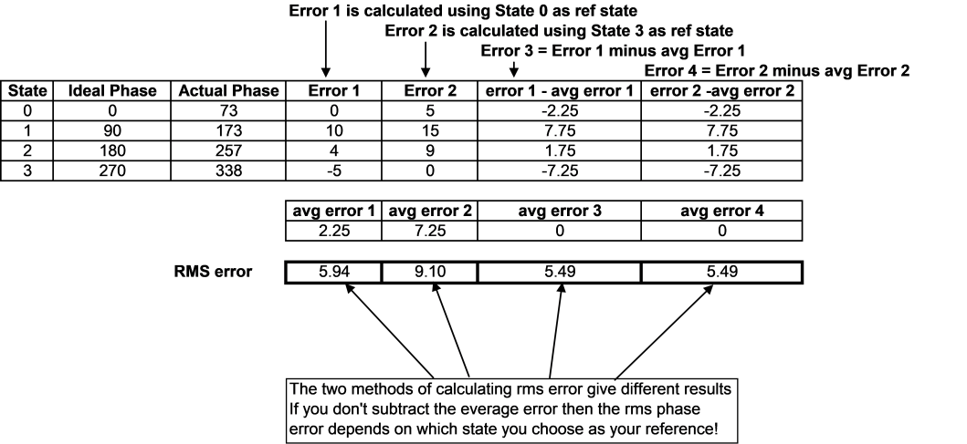
The correct calculation will always result in the lowest figure for RMS phase error and does not depend on choice of reference state.
Amplitude Error
The amplitude cross-error is the difference between the insertion loss (or gain) in a particular state and the insertion loss (gain) in the reference state. The RMS residual amplitude error is then calculated as:

